
Oil-immersed transformers
S13 Oil-immersed distribution transformer
- 6 / 6.3 / 10 kV → 0.4 kV
- 30 – 2500 kVA
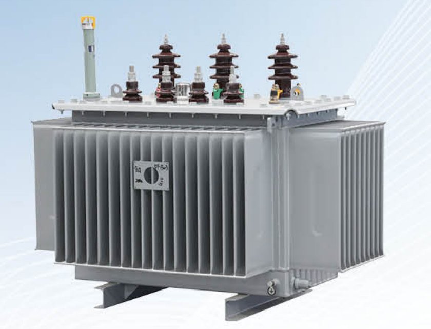
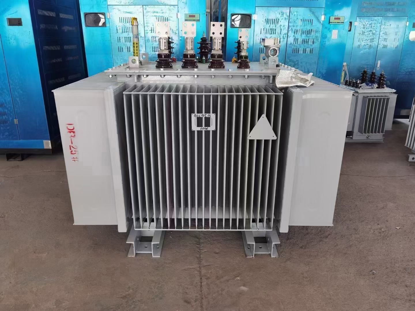
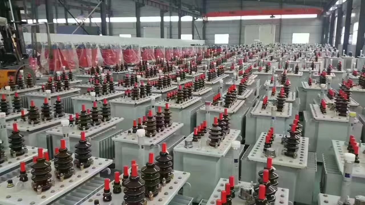
The TMG-100 (factory model S13-M-100) is a hermetic oil-immersed 100 kVA, 10 (6) / 0.4 kV distribution transformer, the step up from TMG-63 for farms, greenhouses and pumping stations outgrowing 63 kVA, and for shops and telecom base stations. Its rated LV current is 144 A, it delivers up to 90 kW at cos φ 0.9, and its no-load loss is 150 W. Price and offer are sent on request within 24 hours.
| Model | S13-M-100 / TMG-100/10/0.4 |
|---|---|
| Rated capacity | 100 kVA |
| HV voltage | 10 / 6.3 / 6 kV |
| LV voltage | 0.4 kV |
| Vector group | Yyn0 or Dyn11 |
| Tapping range (off-circuit tap changer) | ±5% or ±2×2.5% |
| No-load loss | 150 W |
| Load loss (Dy / Yy) | 1580 / 1500 W |
| No-load current | 1.1 % |
| Short-circuit impedance | 4 % |
| Frequency | 50 Hz |
| Cooling | ONAN |
| Design | Hermetically sealed corrugated tank, mineral oil |
| Standards | GB/T 1094 (IEC 60076), GB/T 6451, JB/T 10088 |
| HV rated current at 10 kV | 5.8 A |
|---|---|
| HV rated current at 6 kV | 9.6 A |
| LV rated current at 0.4 kV | 144 A |
| Active power at cos φ = 0.8 / 0.9 / 0.95 | 80 / 90 / 95 kW |
| Recommended continuous load (70–80 % loading, cos φ = 0.9) | 63–72 kW |
| Three-phase short-circuit current at the 0.4 kV terminals (approx.) | 3.6 kA |
Rated current is calculated as I = S / (√3 · U). The short-circuit current is taken as the LV rated current divided by uk, neglecting the supply network impedance. Network and cable impedance lower the actual current, while the uk tolerance (±10 %) and the IEC 60909 voltage factor can raise it by roughly 10 %, so select the breaking capacity of circuit breakers from the short-circuit calculation of the project.
The amorphous-alloy core of the SH15 cuts the no-load loss by 50 % compared with the S13. For one 100 kVA transformer this saves about 657 kWh per year, because no-load loss is present the whole time the transformer is energised, regardless of the load.
| Parameter | S13-M-100 | SH15-M-100 (amorphous) |
|---|---|---|
| No-load loss | 150 W | 75 W |
| Annual no-load energy loss (8760 h) | 1314 kWh | 657 kWh |
| Load loss (Dy) | 1580 W | 1580 W |
| No-load current | 1.1 % | 0.9 % |
| Efficiency at 50 % load, cos φ = 0.9 | 98.80 % | 98.97 % |
| Efficiency at 100 % load, cos φ = 0.9 | 98.11 % | 98.19 % |
| Vector group | Yyn0 or Dyn11 | Dyn11 (Yyn0 on request) |
Efficiency is calculated from the catalogue losses: η = P / (P + P₀ + β²·Pk), where P = β·S·cos φ is the output active power and β is the load factor.
A 100 kVA transformer is typically chosen for sites with a design load of a few tens of kilowatts. On farms and in greenhouses it usually supplies ventilation, heating and lighting; at pumping stations, the pump motors and their control panels; in small shops and workshops, lighting, refrigeration and machine tools; at mobile telecom base stations, rectifiers and air conditioning. The sealed corrugated tank with vacuum oil filling suits such sites, which often operate without permanent staff.
For continuous duty, a loading of 70–80% is a sound target for the TMG-100 (S13-M-100): that is 63–72 kW at cos φ 0.9, leaving headroom for pump motor starting currents and seasonal peaks such as greenhouse supplementary lighting. If the design load fits within 70–80% of the TMG-63 rating, the smaller unit is sufficient and will run in its working range. If the expected load exceeds 72 kW or the site is likely to grow (more pumps, additional greenhouses, a second workshop line), it makes sense to install a TMG-160 from the start rather than replace the transformer a few years later.
Yyn0 is the traditional choice where the load is spread evenly across the phases and the neutral is lightly loaded. At sites typically fed by a 100 kVA transformer the picture is often different: single-phase consumers such as lighting, household appliances, controllers and the UPS units of base stations create phase unbalance and third harmonics. Dyn11 copes better with this kind of load and gives a larger single-phase fault current, which helps protective devices trip reliably on long 0.4 kV feeders. The load losses of the TMG-100 are 1580 W with Dyn11 and 1500 W with Yyn0.
No-load loss is independent of the load and is incurred for all 8760 hours of the year: 150 W or 1314 kWh per year for the S13-M-100, against 75 W and 657 kWh for the amorphous-core SH15-M-100. Where average loading is low or seasonal, as with irrigation pumps, off-season greenhouses or standby supplies, consider SH15, which is Dyn11 as standard; with a three-phase three-limb core, the Yyn0 vector group can also be supplied on request, so state it in your inquiry if you need it. Under high, steady loading the load loss, identical for S13 and SH15 in Dyn11 (1580 W), dominates, and S13 remains a rational choice. Where lower losses than S13 are needed at high loading, choose the energy-efficient S22-M-NX1 series; its 100 kVA version holds a type-test certificate.
The 100 kVA transformer is also supplied as part of a compact substation: ZGS American-type pad-mounted substation (KTPN), up to 1600 kVA, or YB European-type substation (BKTP / GKTP), up to 2500 kVA. The substation is assembled and tested at the factory, so the site work mainly comes down to setting it in place and connecting the cables.
The TMG-100 (S13-M-100) has a rated LV current of 144 A at 0.4 kV. On the HV side the current is 5.8 A at 10 kV and 9.6 A at 6 kV. The incoming circuit breaker and the 0.4 kV cables are selected by the LV current. The three-phase short-circuit current at the LV terminals is about 3.6 kA at nominal uk and an infinite supply. The uk tolerance (±10%) and the IEC 60909 voltage factor can raise the real maximum by roughly 10%, while network and cable impedance lower it, so confirm the breaking capacity of circuit breakers with the project short-circuit calculation (or choose it with margin above 3.6 kA).
At cos φ 0.9 the TMG-100 (S13-M-100) delivers 90 kW of active power at full load (80 kW at cos φ 0.8, 95 kW at cos φ 0.95). For continuous duty a loading of 70–80% is recommended, which means 63–72 kW at cos φ 0.9. This leaves headroom for motor starting currents and load growth, and keeps load losses, which rise with the square of the current, moderate.
The price of the TMG-100 (S13-M-100) is quoted on request only. It depends on the HV voltage, vector group, loss level (S13, amorphous SH15 or energy-efficient S22-M-NX1) and scope of supply, including FOB, CIF or DAP Tashkent terms. We send a technical and commercial offer within 24 hours (one business day) of your request via the website form, email sales@lalogo.uz, Telegram or WhatsApp.
Production of a TMG-100 (S13-M-100) takes 20–35 days after advance payment. Delivery to Tashkent by rail or road via Khorgos or Alashankou and Kazakhstan usually takes 15–25 days. Each unit is supplied with a routine test report, a passport and operation manual in Russian and English, drawings, a packing list and a certificate of origin. A statement of compliance with GOST / OʻzDSt is prepared on request.
The amorphous-core SH15-M-100 has a no-load loss of 75 W versus 150 W for the S13-M-100 (TMG-100), which is 50% lower. Because no-load loss is incurred for all 8760 hours of the year regardless of load, annual no-load losses fall from 1314 kWh to 657 kWh, a saving of 657 kWh per year. Load losses are the same for both models (1580 W with Dyn11), so the benefit is especially noticeable at low average loading.
At 100 kVA a type-test certificate exists for the energy-efficient S22-M-NX1 version (energy-efficiency grade 1 to GB 20052-2020). The standard S13-M-100 (TMG-100) is supplied with a routine test report for every unit, and the manufacturer's management systems are certified to ISO 9001, ISO 14001 and ISO 45001. If your project requires type tests, mention it in your request and we will offer the 100 kVA S22-M-NX1.
Send us the HV voltage, vector group, quantity and delivery point, and we will prepare a technical and commercial offer for the TMG-100 within 24 hours.


