
Oil-immersed transformers
S13 Oil-immersed distribution transformer
- 6 / 6.3 / 10 kV → 0.4 kV
- 30 – 2500 kVA
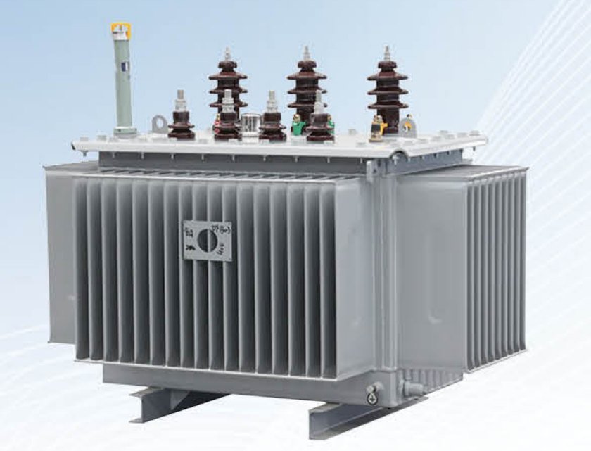
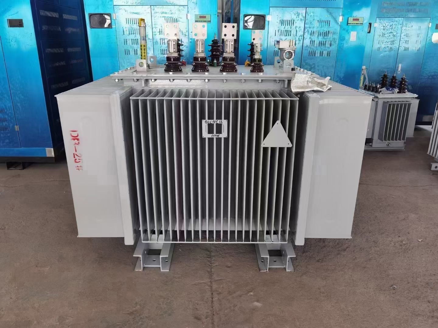
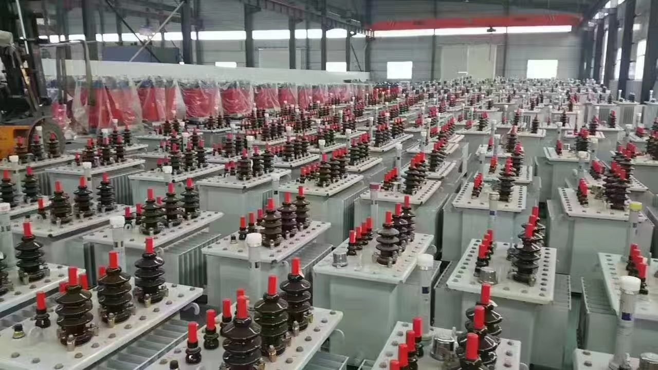
The TMG-630 (S13-M-630) is a hermetically sealed oil-immersed 630 kVA, 10 (6) / 0.4 kV distribution transformer for shopping centres, hospitals and workshops, also installed as 2×630 kVA pairs. LV rated current is 909 A, output 567 kW at cos φ 0.9 and no-load loss 570 W; it is the first S13 rating with 4.5% short-circuit impedance instead of 4%. Price and a techno-commercial offer are sent on request within 24 hours.
| Model | S13-M-630 / TMG-630/10/0.4 |
|---|---|
| Rated capacity | 630 kVA |
| HV voltage | 10 / 6.3 / 6 kV |
| LV voltage | 0.4 kV |
| Vector group | Yyn0 or Dyn11 |
| Tapping range (off-circuit tap changer) | ±5% or ±2×2.5% |
| No-load loss | 570 W |
| Load loss (Dy / Yy) | 6200 / 6200 W |
| No-load current | 0.6 % |
| Short-circuit impedance | 4.5 % |
| Frequency | 50 Hz |
| Cooling | ONAN |
| Design | Hermetically sealed corrugated tank, mineral oil |
| Standards | GB/T 1094 (IEC 60076), GB/T 6451, JB/T 10088 |
| HV rated current at 10 kV | 36.4 A |
|---|---|
| HV rated current at 6 kV | 60.6 A |
| LV rated current at 0.4 kV | 909 A |
| Active power at cos φ = 0.8 / 0.9 / 0.95 | 504 / 567 / 598 kW |
| Recommended continuous load (70–80 % loading, cos φ = 0.9) | 397–454 kW |
| Three-phase short-circuit current at the 0.4 kV terminals (approx.) | 20.2 kA |
Rated current is calculated as I = S / (√3 · U). The short-circuit current is taken as the LV rated current divided by uk, neglecting the supply network impedance. Network and cable impedance lower the actual current, while the uk tolerance (±10 %) and the IEC 60909 voltage factor can raise it by roughly 10 %, so select the breaking capacity of circuit breakers from the short-circuit calculation of the project.
The amorphous-alloy core of the SH15 cuts the no-load loss by 44 % compared with the S13. For one 630 kVA transformer this saves about 2190 kWh per year, because no-load loss is present the whole time the transformer is energised, regardless of the load.
| Parameter | S13-M-630 | SH15-M-630 (amorphous) |
|---|---|---|
| No-load loss | 570 W | 320 W |
| Annual no-load energy loss (8760 h) | 4993 kWh | 2803 kWh |
| Load loss (Dy) | 6200 W | 6200 W |
| No-load current | 0.6 % | 0.3 % |
| Efficiency at 50 % load, cos φ = 0.9 | 99.26 % | 99.34 % |
| Efficiency at 100 % load, cos φ = 0.9 | 98.82 % | 98.86 % |
| Vector group | Yyn0 or Dyn11 | Dyn11 (Yyn0 on request) |
Efficiency is calculated from the catalogue losses: η = P / (P + P₀ + β²·Pk), where P = β·S·cos φ is the output active power and β is the load factor.
A 630 kVA unit is typically chosen for sites with a medium-sized, concentrated load: shopping and office centres, hospitals, production workshops and blocks of multi-storey housing. It is usually installed in indoor transformer substations or in packaged and kiosk-type 10/0.4 kV substations. Where critical consumers need a backup supply, as in hospitals and large shopping centres, two-transformer substations with 2×630 kVA units are the usual arrangement.
At 70–80% loading the TMG-630 carries 397–454 kW of active load at cos φ 0.9, leaving headroom for motor starting currents and load growth. If the design load fits comfortably within a 400 kVA unit, there is little point paying for 630 kVA; if it exceeds 454 kW or the site is expected to expand, consider 1000 kVA or the intermediate 800 kVA rating. Note also that 630 kVA is the first rating in the series with a short-circuit impedance (uk) of 4.5% (400 kVA has 4%): the LV short-circuit current is slightly lower relative to the rated current, while the voltage drop under load is slightly higher.
For the TMG-630 the load loss is 6200 W for both Dy and Yy, so the vector group has no effect on load losses and can be chosen on network grounds alone. Dyn11 copes better with unbalanced single-phase loads and third harmonics, which circulate in the delta winding, and gives a larger single-phase fault current, helping protection operate reliably. In shopping centres, hospitals and residential buildings with many single-phase consumers, lighting and UPS units, this is usually the deciding factor. Yyn0 remains the traditional choice where the load is close to balanced and the neutral is lightly loaded, for example in workshops dominated by three-phase motors.
The choice between S13, the amorphous SH15 and the energy-efficient S-M-NX1 depends on the load profile. No-load loss runs 8760 hours a year: 570 W for the S13-M-630 against 320 W for the SH15-M-630, while load loss is the same for both. Sites with low average loading, such as residential districts, shopping centres with a deep night-time dip or the standby unit of a two-transformer substation, therefore favour SH15, which comes with the Dyn11 vector group as standard; with a three-phase three-limb core, the Yyn0 vector group can also be supplied on request, so state it in the inquiry if you need it. In workshops with steady high loading the difference matters less and S13 remains a sound choice; where a project requires efficiency grade 1 to GB 20052-2020, consider S-M-NX1.
The 630 kVA transformer is also supplied as part of a compact substation: ZGS American-type pad-mounted substation (KTPN), up to 1600 kVA, or YB European-type substation (BKTP / GKTP), up to 2500 kVA. The substation is assembled and tested at the factory, so the site work mainly comes down to setting it in place and connecting the cables.
The TMG-630 (S13-M-630) has an LV rated current of 909 A at 0.4 kV. On the HV side the current is 36.4 A at 10 kV and 60.6 A at 6 kV. The LV current is used to size the incoming circuit breaker and busbars of the 0.4 kV switchboard, and the HV current to select the fuses or protection settings of the 10 (6) kV panel.
At full load the TMG-630 delivers 567 kW at cos φ 0.9 (504 kW at cos φ 0.8 and 598 kW at cos φ 0.95). For continuous duty a loading of 70–80% is usually planned, which corresponds to 397–454 kW at cos φ 0.9. The remaining capacity covers motor starting, seasonal peaks and future load growth.
The price of the TMG-630 (S13-M-630) is quoted on request only, because it depends on the HV voltage, vector group, loss level (S13, amorphous SH15 or S-M-NX1), options, scope of supply and the Incoterms delivery basis. A technical and commercial offer is sent within 24 hours (one business day) via the website form, e-mail sales@lalogo.uz, Telegram or WhatsApp.
Production of a TMG-630 takes 20–35 days after the advance payment, and delivery to Tashkent by rail or road via Khorgos / Alashankou and Kazakhstan usually takes a further 15–25 days. Terms are FOB, CIF or DAP Tashkent. Each unit is supplied with a routine test report, a passport and operation manual in Russian / English, drawings, a packing list and a certificate of origin. A statement of compliance with GOST / O‘zDSt is prepared on request.
The main difference between the TMG-630 (S13-M-630) and the TMG-400 is the short-circuit impedance: 4.5% at 630 kVA against 4% at 400 kVA. The LV fault current of the TMG-630 (about 20.2 kA) is therefore slightly lower relative to its 909 A rated current, while the voltage drop under load is slightly higher. From 630 kVA upward the load loss is also the same for Dyn11 and Yyn0 (6200 W for the TMG-630), so the vector group is chosen on network grounds alone.
At the nominal short-circuit impedance of 4.5% and with an infinite-power supply network (infinite bus), the three-phase short-circuit current at the LV terminals of the TMG-630 is about 20.2 kA. The ±10% tolerance on the impedance and the IEC 60909 voltage factor can raise the real maximum by roughly 10%, while the impedance of the 10 kV network, cables and busbars lowers it. Confirm the breaking capacity of the LV circuit breakers with the project short-circuit calculation, or choose it with a margin above 20.2 kA.
Send us the HV voltage, vector group, quantity and delivery point, and we will prepare a technical and commercial offer for the TMG-630 within 24 hours.


